The Optics Bench
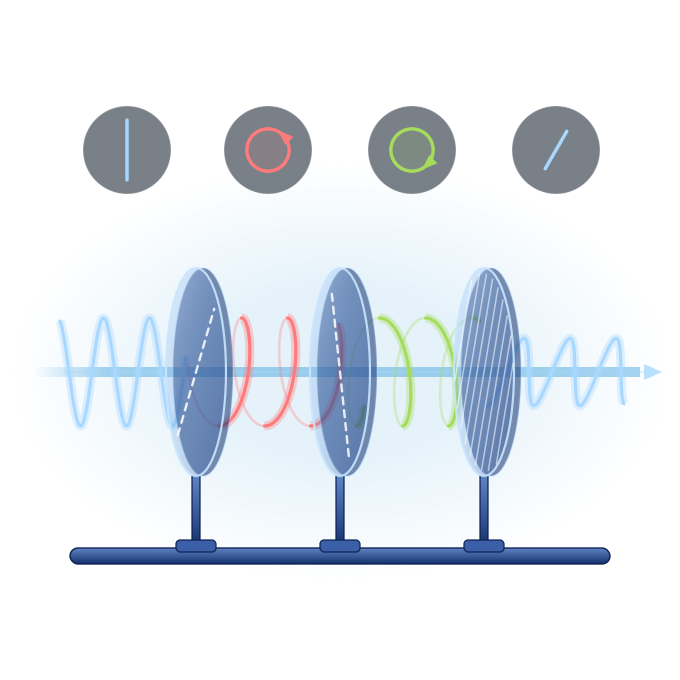
The optics bench: moving light around the sphere
In Part 1 each polarisation state was a point on the Poincaré sphere. Here you change that state with real optical elements: wave plates turn the sphere, polarisers project onto it and depolarisers pull the point inside. Build a bench, watch the path, and discover a phase that comes from geometry alone.
In and out
Matrices
Geometric phase
Conventions and assumptions
The same as Part 1: time dependence e−iωt, S₃ = 2 Im(Ex* Ey), ellipses drawn facing the source. Angles of plates and polarisers are measured from x towards y.
A wave plate with its fast axis at angle ϑ and retardance δ turns the Stokes vector by +δ (right-handed) about the point (cos 2ϑ, sin 2ϑ, 0) on the equator. A rotator by ρ turns it by 2ρ about the S₃ axis.
Jones matrices are written in the symmetric form U = exp(−i δ/2 · n·Σ), with no overall phase. That is what makes the dynamical and geometric phases separate cleanly.
All elements are ideal: a wave plate has exactly the stated retardance at the one wavelength used and loses no light, the beam meets every element at normal incidence, and a polariser blocks the orthogonal state completely. The light is a paraxial, nearly monochromatic beam with the same polarisation all across it.
Partially polarised light always involves an average, over time, over a small range of wavelengths or across the beam; a strictly monochromatic plane wave is fully polarised. The depolariser, M = diag(1, d, d, d), is a mathematical idealisation: real depolarisers scramble the polarisation over wavelength or position, and no single simple element does exactly this.
On the sphere, the solid arcs of wave plates and rotators follow the state as it really evolves inside the element. The dashed lines of polarisers and depolarisers only join the states before and after; the light does not travel along them.
How to use
- Pick a source and add up to six elements. Click an element on the bench to select it and change its angle.
- The coloured arcs on the sphere show what each element does to the state, in the same colours as on the bench.
- The tour steps reset the bench. Free lab keeps whatever you build.
What each element does
Wave plates and rotators are lossless: they turn the sphere, so the point moves on the surface.
Polarisers keep only one state: the point jumps to the polariser's axis and the intensity drops. Depolarisers pull the point towards the centre (an idealised element, see Conventions and assumptions).
Why the geometric phase matters
Take light round a closed loop on the sphere and back to the same polarisation. It returns with an extra phase equal to half the solid angle of the loop. This is the Pancharatnam–Berry phase, discovered by S. Pancharatnam in 1956 and generalised by M. Berry in 1984. Like any phase, it shows up only when the light is compared with a reference beam, for example in an interferometer.
It depends only on the shape of the path, not on how fast you go round it: that is what makes it geometric. It is not a topological invariant, though: deform the loop and the phase changes smoothly with the enclosed solid angle.
Geometric-phase optics uses it in flat lenses, metasurfaces and q-plates. A q-plate makes a spatially varying geometric phase across a beam, which is one of the ways beams like those in Part 3 (polarisation skyrmions) are made in the lab; spatial light modulators and stress-engineered optics are others.
The formulas behind the bench
Wave plate (fast axis ϑ, retardance δ): U = cos(δ/2) 𝟙 − i sin(δ/2) n·Σ, with n = (cos 2ϑ, sin 2ϑ, 0) and n·Σ = [[n₁, n₂ − i n₃], [n₂ + i n₃, −n₁]]. On the sphere: a rotation by δ about n.
Polariser at ϑ: P = ½(𝟙 + a·Σ), transmitted intensity I = ½(1 + p a·ŝ), i.e. Malus's law cos²(γ/2) for fully polarised light, with γ the angle between the points on the sphere.
Depolariser: M = diag(1, d, d, d). Geometric phase of a loop: Φg = −Ω/2, with Ω the enclosed solid angle, counted positive when the loop runs anticlockwise as seen from outside the sphere. Open paths are closed by the shortest arc (Pancharatnam's rule).
This simulation extends Part 1, which is based on an original Mathematica notebook by Prof. Miguel A. Alonso (Institut Fresnel, Centrale Méditerranée & University of Rochester), presented at the POLYTOPO Heraklion Workshop 2026. See the acknowledgement in Part 1.
Yorgis Androulakis, IACM / FORTH
Have a suggestion to improve this simulation?